Honda VFR 750 Regulator / Rectifier
Cooling
VFR 750 Regulator / Rectifier
Cooling
As reported to the Honda VF/VFR Netlist http://www.cs.wisc.edu/~john/vfr-list/
As reports of dead rectifier/regulator units for VFR 750s were on the increase,
and I have a '97 VFR 750, I decided to have a good look at my unit and do
some testing.
I am an electronics engineer by trade, although for the past 10 years I have
been more involved in designing computer networks and moved away from
component/circuit design. ĀI live in Canberra, Australia.
Anecdotal evidence suggested that the rectifier/regulator was running very
hot, and the frame around the unit was also very hot although it was unsure
if it was the frame that was heating up the rectifier/regulator or vice versa.
Preliminary
First I took the bike for an hour's ride through some twisty country roads
and light traffic suburbia, then I measured some temperatures with a digital
thermometer.
All temperatures are Degrees Celsius. ĀFor the members of the list using
Degrees F, to convert from C to F,
F = 1.8 x C + 32
e.g. 69.8C = 157.64F. Ā Ouch!!!
Results
-
Ambient temp. : 26.5 C
-
Rectifier temp. : 69.8 C Ā(can you believe that, no wonder it burns
the F@#$ out of your finger!)
-
Frame temp (top rail of sub frame above rectifier) : 58.3 C (the temperature
of the frame rails drops rapidly the further away from the rectifier/regulator
that measurements are taken so I believe it is the rectifier/regulator that
is shedding heat into the frame).
-
Right side rear cowling temp. : 40.2 (outside wall)
Compare
Observations
-
Electronic components are usually damaged by three things: excessive heat,
vibration and voltage spikes.
-
The heat of the rectifier/regulator unit is quite high, high enough to reduce
the life of the unit. ĀIf this temp is lowered it should extend the
life of the unit (vibration / voltage spikes aside) IMHO.
-
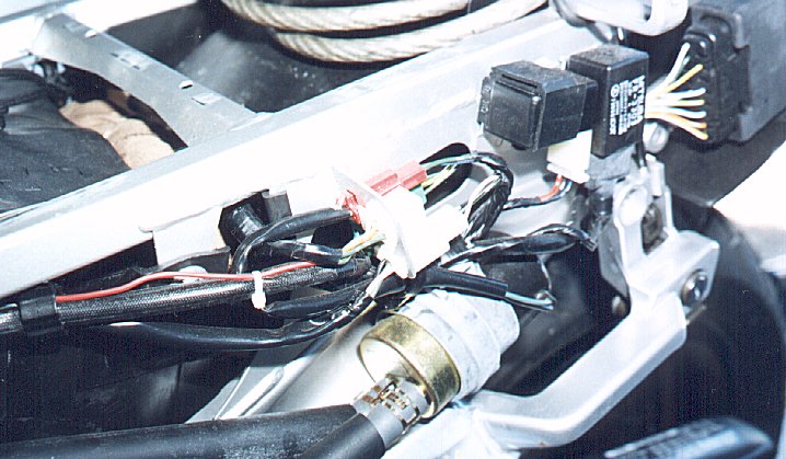
The rectifier/regulator does not mate flush with the frame (slight air gaps)
and is not transferring heat to the frame as efficiently as it couldĀ(hence
the temp. differential between rectifier/regulator and the frame rail).
-
There is about 3.5 inches of clearance between the rectifier/regulator and
the cowling on the 94+ VFR which should allow room for additional heat sinks
to be fitted.
-
1986-89 VFRs have a substantial heat sink included as standard, 1990 models
onwards do not. Ā(This information was derived from the Haynes
workshop manual).
Rectification Attempt 1
-
Applied heat transfer compound between rectifier/regulator and frame to remove
air gaps and improve heat transfer.
Results
-
Ambient temp. : 26.8 C
-
Rectifier temp. : 64.5 C Ā(better)
-
Frame temp. (top rail of sub frame above rectifier) :Ā62.8 C Ā(closer
to the rectifier/regulator temp.)
-
Right side rear cowling temp. : 40.4 Ā(outside wall).
Compare
Rectification Attempt 2
Components
-
Heat transfer compound
-
Passive heat sink (no fan). ĀThis was a heat sink normally used for
power transistors and is 1.75 inches square with "fingers" 2 inches high,
made of aluminium.
Procedure
-
Applied heat transfer compound between rectifier/regulator and frame to remove
air gaps and improve heat transfer.
-
Installed passive heat sink to top of rectifier/regulator with silicon rubber
sealant.
Results
-
Ambient temp. : 27.5 C
-
Rectifier temp. : 55.6 C Ā(better again)
-
Frame temp. (top rail of sub frame above rectifier) :Ā53.9 C
-
Right side rear cowling temp. : 46.4 Ā(getting hotter).
Compare
Rectification Attempt 3
Components
-
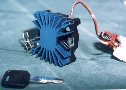
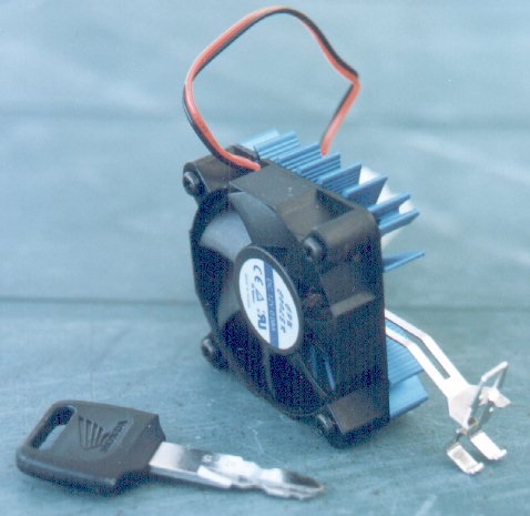
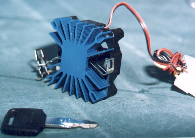
Heat sink assembly. ĀI decided to borrow one of the lists' suggestions
and organised a Pentium PC heat sink and fan assembly (for Pentium 200).

-
Heat transfer compound.
-
Silicon rubber sealant.
Procedure
-
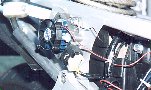
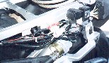
The bottom of the rectifier/regulator has a metal plate, which is used to
transfer heat to the frame. ĀI covered this with enough heat transfer
compound to fill in the air gaps between the rectifier/regulator and the
frame and bolted the unit back onto the frame.
Ā
-
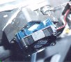
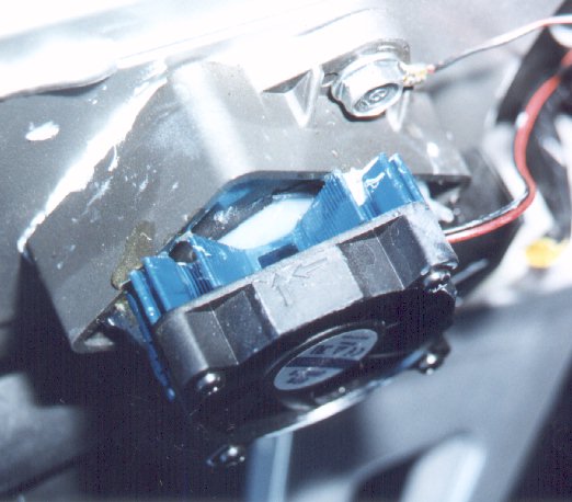
The top of the rectifier/regulator is covered in silicon rubber to protect
the components. ĀI fixed the heat sink assembly to this with silicon
rubber sealant. ĀThe heat sink / fan assembly is large enough to sit
on the metal frame of the rectifier/regulator. ĀApply the silicon rubber
sealant to the centre of the heat sink only, so as not to block the cooling
fins around the rim of the heat sink. Ā(A dab of epoxy resin can be
applied to the corners of the heat sink assembly where it meets the
rectifier/regulator for added adhesion).
Ā
 Ā
Ā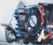
-
Power to the heat sink fan was obtained from the brake light connector (in
Australia, our headlights are wired to be on when the ignition is turned
on. ĀWe don't get a choice). ĀPower for the fan can be taken from
any number of points that are switched byĀthe ignition, asĀthe
fan only draws .08 amps. ĀThe earth was taken from the bolt which fastens
the rectifier/regulator to the frame.
Ā
 Ā
Ā
* The heat sink assembly is only 1 inch high and allows ample clearance to
the rear cowling.
Results
Another 1 hour ride (yeah!!!) on the same roads as before, although the day
had heated up from earlier.
-
Ambient temp. : 29.3 C
-
Rectifier temp. : 44.63C Ā(yes!)
-
Frame temp. :Ā42.5 C
-
Right side rear cowling temp. : 29.5 Ā(seems safe).
Compare
After all this I went out for another ride for about 2 hours with friends.
ĀWhen I got back I measured everything again with almost identical results.
Tentative Conclusion
-
The temp of the rectifier/regulator is about 28 degrees cooler with the heat
transfer compound between the rectifier/regulator and the frame, and the
heat sink and fan installed. ĀThat's got to be a good thing.
-
The rear cowling is actually a little cooler now.
-
This doesn't actually prove a thing, but I am personally more confident that
the rectifier/regulator will last longer.
-
I can't believe that the unit gets that hot as standard!
If anyone has questions / reservations or concerns please raise them.
ĀThere are plenty of inventive minds on the list, and we should be able
to work them out.
Good luck!
Andrew,
Canberra, Australia.
asai@jna.com.au
andysai@msn.com
caradoc@geocities.com
Edwin New's home page (no other VFR content at
present)
Update 13 December 1997 :
-
Temperatures of regulator/rectifier consistent with previous
measurements.
-
Right rear cowling still remaining cool and shows no signs of heat
fatigue.
Appendix : Summary of
temperature readings
Summary of temperature readings
|
Standard |
Heat Transfer Compound (HTC) |
HTC &ĀPassive Heat Sink |
HTC & Heat Sink with Fan |
Difference from Standard |
| Ambient temp. |
26.5 C |
26.8 C |
27.5 C |
29.3 C |
n/a |
| Rectifier temp. |
69.8 C |
64.6 C |
55.6 C |
44.3 C |
-25.5 C / -45.9 F |
| Frame temp. |
58.3 C |
62.8 C |
53.9 C |
42.5 C |
-15.8 C / -28.4 F |
| Cowling temp. |
40.2 C |
40.4 C |
46.4 C |
29.5 C |
-10.7 C /Ā-19.2 F |
Return to article 1 2
3 4
 Ā
Ā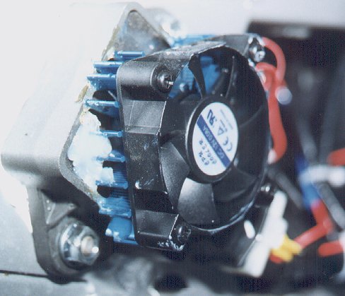
 Ā
Ā